Posts

Basics of capacity Planning in LTE [ Dont ignore VoLte/ViLte Traffic]

  Below  are basics of capacity planning  1. Thumb rule of input is cell throughput or user throughput that derived from below testing . 1.1    How many concurrent users 1.2    What are services we are offering to those concurrent users and what are Min Bit Rate [ UL/DL ] 1.2.1          How many users uses voice-  1.2.2          How many users uses Video 1.2.3          How many users uses Data/OTT 1.2.4          How many users uses Mobile TV 1.2.5          How many users uses TV [ SD & HD ] 1.  2.  How many hours are considered as busy hours out of 24 hours  2.3.  What is data Uses Per Hour DL_MB [ Convert All services into MB 1.2.1 + 1.2.2+1.2.3+1.2.4+1.2.5 ] 4  4.  What is UL Data Volume Per Hour_MB [ Considers as 20% of DL while planning ] 5. 5 .    Total Data Uses_MB :- Point 3+4 6.    6 . How much load Condition data uses_MB :- 70% used as idle Total Data consumption in that total busy hour out of 24 Hrs*70% = Equipped Capacity for that cell Comment i

LTE Layer management Strategy and basic working [LMS] Unlock

Image
LMS Insight Layer Management Parameter Optimization is important aspect & it is triggered when all possible optimization techniques for ensuring best experience to customers is exhausted in the current layer For Example in a typical 3 Layered cellular network, we have LTE layer (with a mix of TDD(2.5GHz) and FDD(1.8GHz)), followed by WDCMA Layer (WCDMA2100) & then the GSM layer (1800 MHz Before actually working on Layer Management Parameter Optimization, we need to ensure Traffic Balancing within the layers is proper & as per recommendations to give desired customer experience Pre-requisite Actions Ensure below checks before moving to optimize the Layer Management Thresholds for a cell. Traffic balancing within layers should be optimal -  if network has 2 layers of LTE i.e. both TDD-20 MHz & FDD-5 MHz, Traffic distribution for collocated cells with TDD/FDD should be 75:25 (TDD: FDD) or better. This is applicable to networks with 2 carriers of WCDMA as well where the tra

Higher Order MIMO Impact in LTE TDD vs FDD[Practical result TDD 2x2 to 4x4 MIMO and FDD 4x4 to 2x2 change]

Image
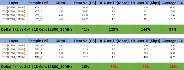
Dear readers you might be wandering for what can be impact while doing changes in MIMO from 2x2 to 4x4 and vice versa  Above table is very easy to understand that how MIMO chaging performance life of cell  All cells Kept for 14 days in their different MIMO scenario and above table prepared in practical scenario  In above table TDD MIMO gain is far-far better than FDD so dont assume higher MIMO will give good gain in FDD  TDD is very well performed after 2x2 to 4x4 conversion where as FDD has some gain in Data Payload as Power /Port increased so Cell radious increased that result more subscriber and subcequent impact in payload , throughput and CQI Below is result of 15MHz TDD L2300 Carrier MIMO change from 2x2 to 4x4  Cells kept for >2WK for observation in 2x2 and 4x4 vice versa . 1. With increased capacity by 70% 2. Payload increased by 41% 3. DL User Throughout increased by 130%  4. UL User Throughout increased by 145% 5. CQI improved by 40% 

Open RAN, Making the RAN flexible, smart and agile [ Telecom industry shift from OEM Centric to Operator Centric]

Image
  Telecom industry has evolve a lot in last 10 years . Open RAN is a shift from OEM centric telecom network to Operator Centric Telecom Network  Monopoly of traditional telecom equipment’s like Nokia/ Ericsson / Samsung /ZTE / Huawei will not more exist [ Earlier who make telecom equipment also makes its software] Open RAN offers verity of options and openness that nontraditional telecom equipment/software companies are taking interest and performing better than traditional OEMs. We can identify that there are major 3 step evolution from traditional RAN to Open RAN when we talk about RAN evolution of 4G/5G specially. We can operate legacy technology 2g/3g with 4g/5g in open RAN concept . Above image is almost self-explanatory with major changes, so if you see it multiple times you will have multiple smile on your face  So Open RAN is a concept that says interfaces are nonproprietary, its open  [  Don’t confuse with O-RAN , O-RAN is an alliance and Open RAN is concept  ] O-RAN alliance

5G Massive MIMO and Beamforming[Analog ,Digital,Hybrid]

Image
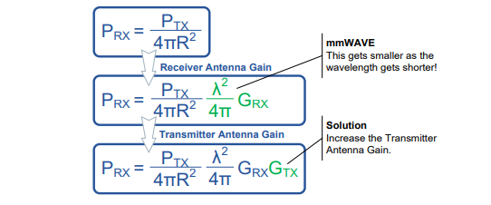
A key part of the 5G NR system relates to the use of Massive MIMO (Multiple Input Multiple Output). The term “Massive MIMO” relates to an antenna array system using a “Massive” amount of antenna elements that can serve multiple users simultaneously. Typically, the number of antenna elements is 128 or 256. How MIMO can compansate issue in 5G Fr So BW is more in 5G for mmWave , so by increasing mimo loss of penetration can be compansated and mimo increment possible in higher frequency as antenna length became smaller From above formula its clear that Prx is directly proportional to Square of wavelength and Gain of receiver and transmiter . How MIMO Can increase capacity From above shannon hartly theorem there are 3 component can impact Capacity  Increase Channels (MIMO):-Utilizing SM (Spatial Multiplexing) enables multiple streams within the same RB (Resource Block). System requires CSI (Channel State Information) Increase Bandwidth:-Existing frequency spectrum is already saturat

e-Band improtance & Key to the 5G Revolution

Image
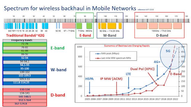
Consumers today demand ever faster wireless. Although wireless engineers have multiple tricks up their sleeves to meet this demand, they can achieve  only so much. To deliver the gigs customers crave, more spectrum is required V band (60 GHz) and E band (70/80 GHz) are open to all , with abundant spectrum available to deliver on the promises of 5G. Good news for india is that probably with 5G spctrum allocation E-Band will be alloted to 5G spectrum buyers along with 3.5GHz or 26GHz spectrum for backhaul of 5G Radios  The 60 GHz V band, which is unlicensed, has 14 GHz of contiguous spectrum (57 GHz to 71 GHz). The 70/80 GHz paired E band adds another 10 GHz of spectrum for a total of 24 GHz. These V and E bands are open to everyone, and equipment for them is available today from a rich ecosystem of suppliers. Below are some statistic from IMT-2020  During past 10 years microwave BH evolution describe below points  1. MW capacity needs for Mobile  Operators increased x 15 for delivering 

LTE Vs NR[EN-DC] Coverage and throughput observation with 8x8 ,32x32 & 64x64 Scenario

Image
Hello readers there are multiple questions about 5G/NR future in india as trials are only carried out by all major 3 operators  with help of Major 3 OEMs  Ericsson , Nokia & Samsung with restriction of 30 eNB per scenario[Urban , Rural , Semi Urban] in a PLMN  Below is some basics of measurement difference Jio is doing trails with indegenious system so they have adavantage of doing trials on 300 eNB per scenario in PLMN as per letter of Ministry of communication and they are doing trials . So one question is genuine that which 5G/NR options will be adopted by all 3 operators of india and answer is very simple and its Option3x . As still out of 3 , 2 operators are not willing to loose 2G customer and hence  there is no way of thinking of loosing 4G customer by deploying Option2 is  5G/NR SA  with additional massive investment . I will not go into details  but overview is that Option3x is future of 5G/NR in india  Option3x has advantage that with same Core, operators will be able to

LTE/NR PCI Conflict , PCI Confusion,PCI Collision, Mod of PCIs- 3,4,6,30

Image
Dear readers as per above snap its easy to say PCI confusion and Collision coming under PCI conflict and reaspective reasons that mentioned in snap . Each 5G/4G cell corresponds to a Physical Cell ID (PCI) and it is used to distinguish cells on the radio side. The PCI planning for 5G NR is very much similar to PCI planning for LTE and scrambling code planning for 3G UMTS. Bad or wrong planning can affect the synchronization procedure , demodulation, and handover signalling and degrade the network performs. PCI Planning should be simpler for NR compare to LTE because there are double as many PCIs available for allocation While Planning PCI , below things need to follow strictly  1. Nbr cell should not have same position of PSS  2. Nbr Cell can use same SSS position  3. Intra Cells of an eNB should not have same PCI in same carrier  As PCI is derived from PSS and SSS so there should not be same position of PSS &SSS combination of cells on their different Antenna Port . For example fo

4G/5G TA/TAL Planning Principle

 TA/TAL Planning Principle The TAC or TAL planning for 5G is similar to 4G. Infact, as the current 5G NR will be using the NSA mode, so initially it should be using the same TAC or TAL as the 4G network. However, the principles for TAC planning are same as given below The paging load should be calculated to ensure that the TAC is not so big that the paging overhead gets too high. This issue is usually mitigated with the intelligent/dynamic/precise paging features If the TAC is too small, this will result in a lot of TAUs that can generate signaling overheads. This can be handled by intelligent TAL planning or even user specific dynamic TAL assignments Some of thumb ruple w.r.t absolute counts  1. When do TA/TAL planning, need guarantee the TAs do not overlap in different TAL. 2. Suggested TA size do not keep too big, so when do TAL optimization , configuration adjusting is flexible ; 3. Suggested a TA including 30~70 eNBs, and TAL including 3~10 TAL; 4. If operator have 2G/3G network,

RAN CQI and Traffic ,Utilization Variation

Image
  Above stats of variation of CQI vs utilization and traffic is self explanatory that yes CQI will get detoriated with increase inpayload as well as PRB utilization >60% Utilization is critical as latency increases exponentially along with almost 3% degradation in cqi with 1% increase in utlization 

Satellite internet understanding and its impact in future communication system

Image
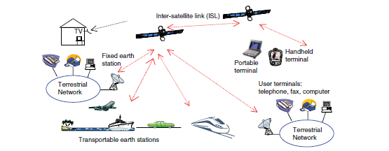
Above ref:- Satellite Communication system by GERAND MARAL|MICHEL BOUSQUET|ZHILI SUN There are basic 5 building blocks for satellite internet shown in image. Satellite internet is wireless internet beamed down from satellites orbiting the Earth. It’s a lot different from land-based internet services like cable or DSL, which transmit data through wires. Since it’s the only internet service that’s available nationwide, satellite internet is often the only way to get online for many rural homes and businesses, although it does still come with a few disadvantages like live gaming or services which require less latency . Satellite comminication main moto to make signal available at each and every point of earth. There are 3 types of satellite  I am assuming that how a satellite can cover earth area depending upon its height from earth , means higher the atltitude possibility of covering earth from lesser no of satellites and lower the altitude higer no of satellite required to cover earth

RRC Improvement : RRC Fail due to Timer Expiry(SIGN_EST_F_RRCCOMPL_MISSING)

Image
On Counter level analysis its found that almost 98% RRC failures are contribution from timer expiry As all other timers were already in GPL at Max values with  tHalfRrcCon (eNB internal timer) :-default value 3000ms. This timer in Nokia was hardcoded in earlier SW version Trial Impact 3s to 4s Data Traffic increased by 1.8% and Volte traffic by 9.8% 3% Cells with RRC<98% improved in BBH 17% Cell with RRC<98% Improved in 24 Hrs 9% reduction in timer expiry RRC failures  Rest all KPIs are intact and almost no changes in stats 

TCP Service Differentiation | Solution for High Congested Cells where resource addition delay

Image
With this functionality enabled, Packet Data Convergence Protocol (PDCP) layer is monitored for TCP traffic. From the moment it is detected, the BTS starts measuring volume of TCP data (only TCP packet with size equal or bigger than the LNCEL Minimum TCP packet size (minTcpPacketSize) parameter are considered for this measurement). Two thresholds are defined Lower and Upper for UL and DL both After reaching lower threshold, the scheduling bias is applied, resulting in a boost of data transfer. After reaching upper threshold, the bias application is stopped, and data transfer is not boosted anymore Trial Result  1. Data Traffic Increased by 1% 2. Volte Traffic Increased by 8% 3. %Cells CQI<8 reduced by 6% 4. %Cells RRC SR>98% increased by 5% 5. %Cells RAB SR>98% Increased by 3% 6. %Cells PS Drop>0.9% reduced by 31% 7. %Cells with DL User Throughput<2Mbps reduced by 17%

CQI Improvement PDCCH CQI Shift for 4Tx [TDD Nokia ]

Image
It was discovered that 4Tx Transmit Diversity results in up to 1 dB performance penalty compared to 2Tx Transmit Diversity. Therefore, an offset for mentioned algorithm is needed to allow a slightly more conservative choice of aggregation level with 4Tx and that offset is pdcchCqiShift4Tx  Trail Result for pdcchCqiShift4Tx =-1.5 for Nokia 

RLF inhancement feature and its impact on Volte KPIs

Image
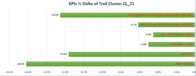
In normal procedure after T310 expire RLF trigger and UE context should  get restored within T311  Normal RLF trigger HO start before T311 expiry( UE context information available with Source eNB and MME) , In Enhanced RLF trigger case UE context information available with Target eNB via MME from source eNB so in that case reestablishments success chance is more w.r.t normal RLF trigger Handover LTE3105: RLF Triggered HO Enhancements feature improves call drop rate by allowing radio link failure (RLF) triggered handovers during ongoing RRC reconfiguration procedures Impact of testing  VoLTE DCR  reduced by 13.6% VoLTE Mute Call Rate reduced by 5% No of Cells with VoLTE drop call rate >1% [CBBH] reduced by 6%  No of Cells with VoLTE RAB Setup Success Rate <98%[CBBH] reduced by 14% 

DL mimomode of SRB1 change impact on accessibility

Image
LTE2026: RRC Signaling Robustness -feature provides an increase in the reliability of the downlink radio resource control (RRC) signaling messages on the physical downlink shared channel (PDSCH) and the physical downlink control channel (PDCCH) to reduce the latency for the RRC procedures and to improve call setup and handover (HO) success rates. dlSrbMimoMode :- This parameter determines the MIMO mode to be used for Downlink SRB traffic  1: TxDiv  2: SpatialMultiplexing Suggestion:- purpose of changes that SRB1 do not required capacity so we can use dlmimomode tx diversity instead of special multiplexing so that dl can be more reliable and that can give benefit in success rate I did changes for worst cells in my network from special multiplexing to TX diversity and good improvement seen 

MIMO and TM( Transmission Mode) in LTE

Image
4G Americas have published whitepaper titled "MIMO and Smart Antennas for Mobile Broadband Systems" . The above picture and the following is from that whitepaper Actually MIMO operation is Subset of diffirent Transmission Mode(TM) Below are some terminology used and their meaning  MIMO  :- MIMO is a method for multiplying the capacity of a radio link using multiple transmission and receiving antennas  to exploit multipath propagation ,  it is being  used in Wi-Fi , 3G (HSDPA+) , LTE , LTE-A(4G) MIMO systems are used to improve the robustness of data transmission or to increase data rates. Typically, a MIMO system(MxN) consists of m transmit antennas and n receive antennas SU-MIMO:-  It will provide multiple layers of communications to a handset for increasing of throughput. Each communication layer added to the User will increase the final throughput based on number of layers. Extra layers are been added using extra antennas in space diversity and more Transmitters in Base-st