Posts

Volte MOS and Throughput Vs Coverage in LTE

Image
What is poorest RSRP to deliver Service in LTE Hi readers you might be come across a situation when people can ask what will minimum RSRP to deliver good voice experience and throughput  Below are DT observation of one of metro in India with dense clutter  Average SINR - 5.3 Average PRB Utlization - 58.2 % Volte MOS Vs RSRP  Volte MOS always Good (>3.5) when coverage better than -105/-106 dBm There is drastically degradation in MOS post RSRP -105dBm  LTE User Throughput  Vs RSRP  User throughput always good (>3Mbps) when RSRP better than -110dBm -85/-95dBm is best delivery of throughout at reference RSRP Post -100dBm throughput start degrading more frequently

5G [RF1/FR2] Cell site TX Bandwidth Dimensioning

Image
  Above are table prepared for 5G FR1/FR2 along with LTE transport bandwidth dimensioning outcome  Formulae Invole  Peak Cell DL TP_Gbps=(BW*SPE*(1+0.1)*DL Share)/1000  { 0.1 is Overhead} Average Cell DL TP_Gbps=(BW*SPE*(1+0.1)*DL Share)/1000  { 0.1 is Overhead} Peak Transport BW_Gbps=Peak Cell DL TP_Gbps+(N-1)*Average Cell DL TP_Gbps { N is no of Cells} Average Transport BW_Gbps=N*Average Cell DL TP_Gbps{ N is no of Cells} Note:- In initial phase of deployement, there are two option to dimention TX bandwidth  1. Cell throughput as above  2. Single user Cell Throughput  approx. equal  Single User Throughput  So there may be 2 types of operator  Who do not afford for a regressive testing for required capacity   They can user single user throughput as Cell throughput in above formulae to calcultae TX BW requirement  Who wish to design and do proper dimensioning below steps need to take  How many concurrent users can handle by OEM/Operator and what  are agreegation of minimum bit rate [DL

5G NSA Layering Design Guideline

Image
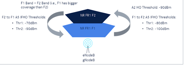
Deployment of 5G network can have different combination of technology i.e., NSA (Non-Stand-alone) and SA (Stand-alone), different band combinations and various number of frequency layers.Below details will be limited to NSA ENDC deployments only Multilayer Strategy Selection-different factors 1.Functionality or Performance of existing network The layering strategy maybe need to be aligned with the existing LTE network when 5G is introduced. For instance, in the early-stage coverage maybe more important than throughput. From commercial aspect the 5G symbol on the subscribers' UE maybe important.In other cases, the NR layer maybe used to offload congested LTE layers, thus pushing LTE users from a specific LTE layer to anchor layer (ENDC) or straight to NR (for SA). The choice or preference of LTE layer in certain clutter will also determine the choice of NR layer for the case of ENDC. For example, in rural area LTE 900 maybe preferred due to coverage, thus only NR layers that can be

Smartphones - Can they Handle the Heat of 5G?lllSmartphones Overheating on 5G|smartviser.com

Image
SmartViser team have done several smartphones testing  in  lab ranging from entry-level to flagship, with various chipsets from Qualcomm to Exynos and MediaTek. Several smartphones overheated after only 20 minutes of operation while in 5G, despite all testing performed exactly in the same conditions. These conditions included aspects of the environment like an office with Air Con at 16 degrees Celsius as well as ensuring the same network conditions with good 5G coverage. SmartViser team testing results for the smartphones identified 3 main groups: GROUP 1 Smartphone did not overheat and continued with the data transfer for the duration of the testing.  GROUP 2 The smartphone reached 48 degrees after 20 minutes. As the temperature continued to increase, the smartphone displayed an error message. The image below shows how the temperature was rising in correlation with the data throughput usage. Group 3 This group was the most interesting one for results. The smartphones switc

Subscriber Churn Reason in Telecommunication

Image
What’s predicting churn in Telecommunications apart from tariff Plans What Churn[Port Out ] figure says in India Actual Scenario :- Operator AA-62% Churn towards Operator -BJ and 37% towards Operator- CV RCA-1.Whichever customer move from AA to BJ/CV operator through port out process 43% was unsatisfied with AA network and 46% due to differential tariff plans and 11% didn't concluded RCA-2. 43% of AA operator which was churn towards BJ/CV due to network related issue 17% was facing indoor coverage issue and 12% was expecting unlimited 5G that BJ was offering  ] Conclusion :- Out of 100 churn from AA towards BJ/CV , 43 were experienced network issue and 46 having tariff plan issue . out of 43 churn due to network , 17 contribution towards coverage and 12 with Unlimited 5G  expectation . So we should add these 12 cases into tariff plans so final tally are below  Business Matrix/Tariff Plan  - 46+12 =58 Network Matrix- 43-12=31 [ Indoor Coverage- 17 , Voice/Data Exp-14 ] What Demogra

Activate Automatic MCS Upgrade [actMcsUpgrade] for LTE throughput Improvement

Image
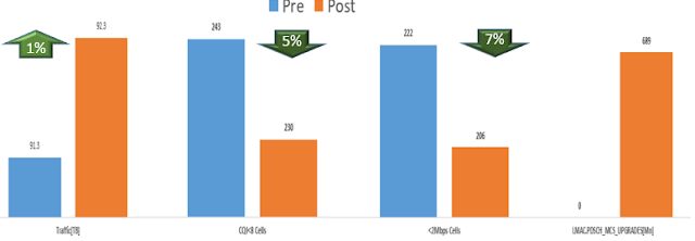
Activates downlink MCS Upgrade functionality for non-GBR transmissions and specifies if the upgrades can increase the MCS index by one or two. The purpose of this function is to improve over the air spectral efficiency. Full RBG allocations (RAT0) are used for DL scheduling. This leads to spectrally inefficient allocations when a partial RBG is needed to drain a UE's buffer.  For example in a 20 MHz system if 5 PRBs are required to drain a UE's buffer, an allocation of two RBGs is required, i.e. 8 PRBs. If MCS Upgrade is enabled, an MCS upgrade will be used so that an allocation of one full RBG (4 PRBs) can be used to drain the UE's buffer. MCS upgrades are only used to reduce a 3 RBG allocation to 2 RBGs or to reduce a 2 RBG allocation to 1 RBG actMcsUpgrade[Activate MCS upgrade]    For Nokia OEM Paramter name is actMcsUpgrade which has different values as below  0: Disabled 1: SingleMcsIndexUpgradeOnly  2: SingleOrDoubleMcsIndexUpgrade Above Pre-Post snap is one of cluste

A-Smart Tower Move towards “0” energy cost of sites

Image
 

GTP Loss and Impact of Transport Bandwidth

Image
Above is practical result of Transport Bandwidth Change impact and its difficult to isolate throgh OSS KPIs , It needs GTP analysis along with field testing  1. Site was already congested and >95% Radio Capacity was used  2. By Changing Transport BW from 200Mbps to 400Mbps site comsumes more 20% traffic with 110% Radio capacity used and better performance . 3. There is no impact seen in OSS KPIs but field test shows >85% throghput degradation. 4. Packet loss and Latency was all across reason for user experiance degradation. 5. One Major thumb rule that i came across that                            Transport BW  > (Sum of Cell throughput of site ) * 118% What is GTP  and GTP Loss ? 1. GPRS Tunneling protocol is an important IP based protocol used in GSM, UMTS and LTE core networks. It is used to encapsulate user data when passing through core network and also carries bearer specific signaling traffic between various core network entities. 2. It provides mobility. When UE is mob

Self Interference(SI) and 5G-4G Interworking Challenge in NSA [Why EN-DC of B3 is not favourable with N78]

Image
We are not operating on single RAT!!!!!!! Invitation of IMD[ intermodulation distortion] When multiple air interface technologies coexist, mutual interference will inevitably occur between different working frequency bands (for the same device, we call this interference “self-interference (SI)”) As a typical heterogeneous network, the fifth generation (5G) mobile communication system must be compatible with existing technologies (such as Long-Term Evolution (LTE)) and support multiple types of 5G New Radio (5G NR) so SI will came in picture everywhere  As device is same and its competible for multi RAT then it creates Harmonics as a result of SI Even/Odd Harmonics  Intermodulation (IM) or intermodulation distortion (IMD) is the amplitude modulation of signals containing two or more different frequencies, caused by nonlinearities or time variance in a system. The intermodulation between frequency components will form additional components at frequencies that are not just at harmonic fre

PDSCH Resource distribution in TDD and FDD

Image
  Hello readers many of us will be wandring and might be struggling to take decission for which LTE technology and MIMO you should prefer fo capacity  In earlier blog  https://mytelcolearning.blogspot.com/2022/04/basics-of-capacity-planning-in-lte-dont.html i had described basic of capacity planning guideline  As PDSCH is the main resource used for >94% data uses by any means in downlink Total Data Volume[100%] = DL[>94%] +UL [<6%] So lets have a view on above resource distribution details along with Channel Bandwidth and MIMO One Major Takaway in terms of PDSCH availability 15MHz 4x4 TDD will have same capacity as 10MHz 2x2FDD

CPRI & eCPRI with Open RAN Split Option 8 and 7-2x

Image
Importance of Simplified RU A simplified RU because only the RF functions remain at the remote site. This small RU costs less, uses less power, and more easily fits on a tower. Operators can perform most network upgrades at the CU, requiring fewer site visits. The simplified RU can handle multiple Radio Access Technologies (RAT) further reducing the footprint of the remote mast, which must support multiple cellular generations There are 2 types of protocol used for fronthaul between RE/eRE to REC/eRCE these protocols are CPRI and eCPRI The Purpose of development of CPRI and eCPRI is as follows.  Radio BSs should offer flexibility during deployment to MNOs( mobile network operators). This is achieved by simplifying BS architecture by dividing radio BS functionality into two modules viz. eREC and eRE. Both parts may be physically separated where in eRE is kept close to RF antenna where as eREC kept at a distant end. Both are connected via a transport network. The eREC contains part of PH

Basics of capacity Planning in LTE [ Dont ignore VoLte/ViLte Traffic]

  Below  are basics of capacity planning  1. Thumb rule of input is cell throughput or user throughput that derived from below testing . 1.1    How many concurrent users 1.2    What are services we are offering to those concurrent users and what are Min Bit Rate [ UL/DL ] 1.2.1          How many users uses voice-  1.2.2          How many users uses Video 1.2.3          How many users uses Data/OTT 1.2.4          How many users uses Mobile TV 1.2.5          How many users uses TV [ SD & HD ] 1.  2.  How many hours are considered as busy hours out of 24 hours  2.3.  What is data Uses Per Hour DL_MB [ Convert All services into MB 1.2.1 + 1.2.2+1.2.3+1.2.4+1.2.5 ] 4  4.  What is UL Data Volume Per Hour_MB [ Considers as 20% of DL while planning ] 5. 5 .    Total Data Uses_MB :- Point 3+4 6.    6 . How much load Condition data uses_MB :- 70% used as idle Total Data consumption in that total busy hour out of 24 Hrs*70% = Equipped Capacity for that cell Comment i

LTE Layer management Strategy and basic working [LMS] Unlock

Image
LMS Insight Layer Management Parameter Optimization is important aspect & it is triggered when all possible optimization techniques for ensuring best experience to customers is exhausted in the current layer For Example in a typical 3 Layered cellular network, we have LTE layer (with a mix of TDD(2.5GHz) and FDD(1.8GHz)), followed by WDCMA Layer (WCDMA2100) & then the GSM layer (1800 MHz Before actually working on Layer Management Parameter Optimization, we need to ensure Traffic Balancing within the layers is proper & as per recommendations to give desired customer experience Pre-requisite Actions Ensure below checks before moving to optimize the Layer Management Thresholds for a cell. Traffic balancing within layers should be optimal -  if network has 2 layers of LTE i.e. both TDD-20 MHz & FDD-5 MHz, Traffic distribution for collocated cells with TDD/FDD should be 75:25 (TDD: FDD) or better. This is applicable to networks with 2 carriers of WCDMA as well where the tra

Higher Order MIMO Impact in LTE TDD vs FDD[Practical result TDD 2x2 to 4x4 MIMO and FDD 4x4 to 2x2 change]

Image
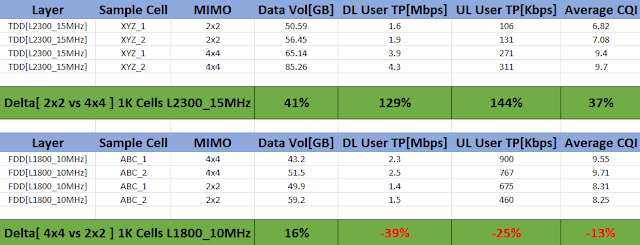
Dear readers you might be wandering for what can be impact while doing changes in MIMO from 2x2 to 4x4 and vice versa  Above table is very easy to understand that how MIMO chaging performance life of cell  All cells Kept for 14 days in their different MIMO scenario and above table prepared in practical scenario  In above table TDD MIMO gain is far-far better than FDD so dont assume higher MIMO will give good gain in FDD  TDD is very well performed after 2x2 to 4x4 conversion where as FDD has some gain in Data Payload as Power /Port increased so Cell radious increased that result more subscriber and subcequent impact in payload , throughput and CQI Below is result of 15MHz TDD L2300 Carrier MIMO change from 2x2 to 4x4  Cells kept for >2WK for observation in 2x2 and 4x4 vice versa . 1. With increased capacity by 70% 2. Payload increased by 41% 3. DL User Throughout increased by 130%  4. UL User Throughout increased by 145% 5. CQI improved by 40% 

Open RAN, Making the RAN flexible, smart and agile [ Telecom industry shift from OEM Centric to Operator Centric]

Image
  Telecom industry has evolve a lot in last 10 years . Open RAN is a shift from OEM centric telecom network to Operator Centric Telecom Network  Monopoly of traditional telecom equipment’s like Nokia/ Ericsson / Samsung /ZTE / Huawei will not more exist [ Earlier who make telecom equipment also makes its software] Open RAN offers verity of options and openness that nontraditional telecom equipment/software companies are taking interest and performing better than traditional OEMs. We can identify that there are major 3 step evolution from traditional RAN to Open RAN when we talk about RAN evolution of 4G/5G specially. We can operate legacy technology 2g/3g with 4g/5g in open RAN concept . Above image is almost self-explanatory with major changes, so if you see it multiple times you will have multiple smile on your face  So Open RAN is a concept that says interfaces are nonproprietary, its open  [  Don’t confuse with O-RAN , O-RAN is an alliance and Open RAN is concept  ] O-RAN alliance

5G Massive MIMO and Beamforming[Analog ,Digital,Hybrid]

Image
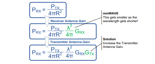
A key part of the 5G NR system relates to the use of Massive MIMO (Multiple Input Multiple Output). The term “Massive MIMO” relates to an antenna array system using a “Massive” amount of antenna elements that can serve multiple users simultaneously. Typically, the number of antenna elements is 128 or 256. How MIMO can compansate issue in 5G Fr So BW is more in 5G for mmWave , so by increasing mimo loss of penetration can be compansated and mimo increment possible in higher frequency as antenna length became smaller From above formula its clear that Prx is directly proportional to Square of wavelength and Gain of receiver and transmiter . How MIMO Can increase capacity From above shannon hartly theorem there are 3 component can impact Capacity  Increase Channels (MIMO):-Utilizing SM (Spatial Multiplexing) enables multiple streams within the same RB (Resource Block). System requires CSI (Channel State Information) Increase Bandwidth:-Existing frequency spectrum is already saturat

e-Band improtance & Key to the 5G Revolution

Image
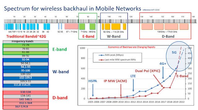
Consumers today demand ever faster wireless. Although wireless engineers have multiple tricks up their sleeves to meet this demand, they can achieve  only so much. To deliver the gigs customers crave, more spectrum is required V band (60 GHz) and E band (70/80 GHz) are open to all , with abundant spectrum available to deliver on the promises of 5G. Good news for india is that probably with 5G spctrum allocation E-Band will be alloted to 5G spectrum buyers along with 3.5GHz or 26GHz spectrum for backhaul of 5G Radios  The 60 GHz V band, which is unlicensed, has 14 GHz of contiguous spectrum (57 GHz to 71 GHz). The 70/80 GHz paired E band adds another 10 GHz of spectrum for a total of 24 GHz. These V and E bands are open to everyone, and equipment for them is available today from a rich ecosystem of suppliers. Below are some statistic from IMT-2020  During past 10 years microwave BH evolution describe below points  1. MW capacity needs for Mobile  Operators increased x 15 for delivering